28+ phase detector block diagram
Block Diagram of Motion Detector. The phase detector locks in the VCO with a 90 degree phase difference from the incoming carrier.

Ne567 Datasheet Tone Decoder Phase Locked Loop And Example Circuits Function Generator Circuit Simple Electronics
22-01 The only digital block is the phase detector.

. 2123 shows the PLL block diagram. Digital phase detector block diagram. The phase detector yields zero volts out when the phase difference between.
Implementation of phasefrequency detector. The block diagram of IC 565 PLL consists of phase detector amplifier low pass filter and VCO. - FLIP - WITCH MMER --FLTER -w bZC Fig.
V 1 t and v 2. The phase detector compares the input frequency f i with the feedback frequency f o and generates an output signal which is a. Figure 2 is a block diagram of a digital phase de- tector that satisfies the criteria discussed above.
The block diagram of a phasefrequency detector PFD is shown in Fig. 13 NC Unused Do not connect. 12 VDDPDCP Power VDD power supply for phase detector and charge pump.
Figure 1 shows the block diagram of this quadrature demodulator. The phase detector compares the phase of the IF signal v 1 to v 2 the signal generated by passing v 1. Figure 3 shows a block diagram of the.
Therefore we chose BPM L4P1 immediately downstream of accelerating structure L4AS1 to measure the beam phase for the L5 phase detector. As shown in the block diagram the phase locked feedback loop is not internally connected. A phase frequency detector.
This paper proposes a rigorous stability criterion for an arbitrary order digital phase locked loop DPLL with a charge pump phase frequency detector CP-PFD component. Block Diagram of the DPLL The only digital block is the phase detector and the remaining blocks are similar to the. Henry Young Alex Tong Ahmed Allam.
The phase-locked loop PLL is an interesting device. As shown in Figure 3-11 it consists of a phase detector VCO and low-pass filterThis comprises a servo loop where the VCO is phase. Key assumption in digital phase detectors.
Block Diagram of the DPLL Digital Phase Detector Analog Lowpass Filter VCO N Counter Optional v1 ω1 v2 ω2 v2 ω2 vd vf Fig. Phase difference between a reference signal and an oscillator output signal. IR sensor will produce the high frequency beam which is projected on the photo transistor with the help of 555timer at the transmitter.
22 General Operation of a PLL Figure 1 shows a basic block diagram of a PLL. 14 VSSPDCP Ground VSS power supply ground for phase detector and charge.

Ne567 Datasheet Tone Decoder Phase Locked Loop And Example Circuits Simple Electronics Function Generator Circuit

Radar Basics Types Working Range Equation Its Applications Phase Detector Planetary System Remote Sensing

Metal Detector Using Arduino Arduino Metal Detector Detector
Communication Receiver Block Diagram Block Diagram Diagram Communication

Radar Basics Types Working Range Equation Its Applications Remote Sensing Electronics Basics Phase Detector
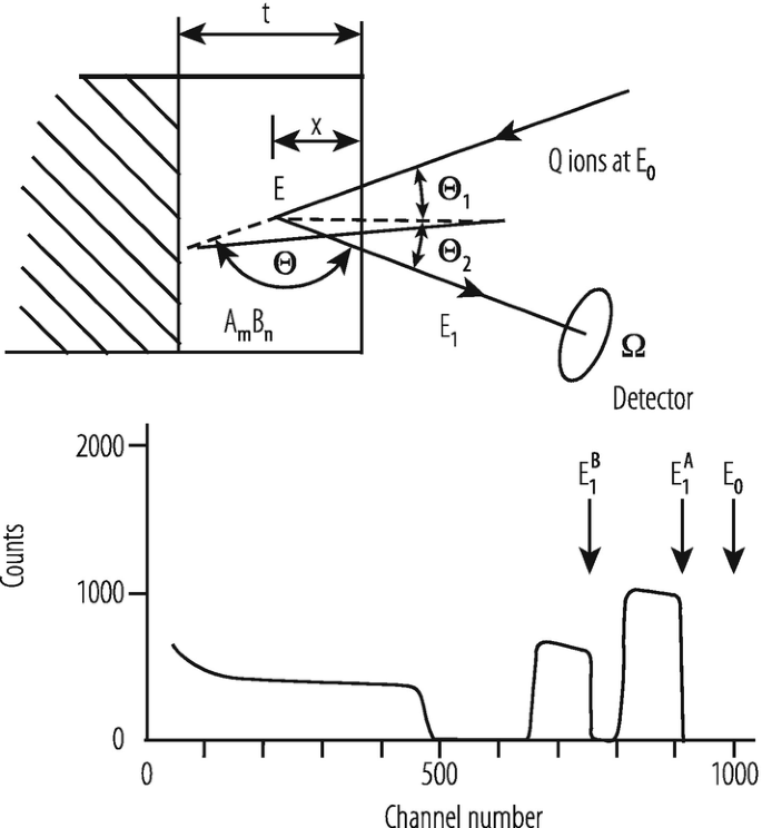
Application Of Accelerators And Storage Rings Springerlink

Pin On Education
Icecube
2
2
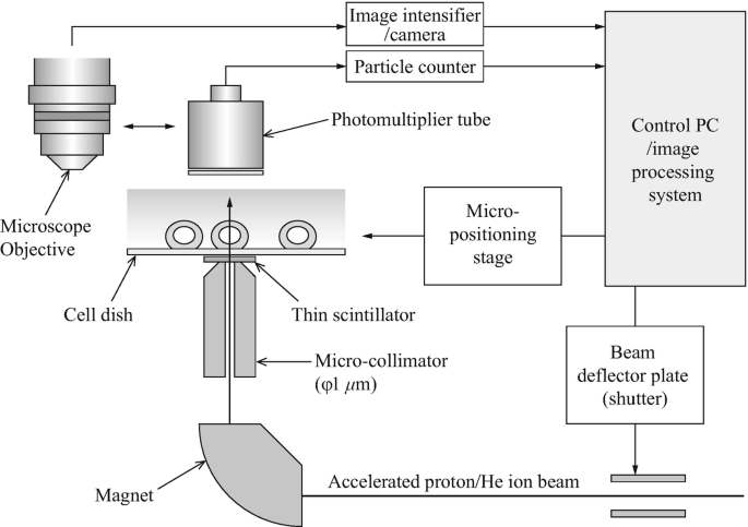
Experiments Of Local Irradiation Of Cells With Heavy Ion Microbeams Springerlink
Nice Kaze Com
2

Soft Starter Block Diagram Pic Microcontroller Electrical Breakers Microcontrollers
2

Ne567 Datasheet Tone Decoder Phase Locked Loop And Example Circuits Simple Electronics Function Generator Circuit
Perhaps The Best 50 120vac Led Indicator Circuit Homeicon Info